Part 4: Designing a Scalable Cisco Network Topology: Spanning Tree Protocol (STP) to Prevent Loops and Ensure Network Stability
 Suresh Thapa
In a switched network with redundant links, Layer 2 loops can cause broadcast storms, MAC table instability, and complete network failure. To prevent this, Cisco switches use the Spanning Tree Protocol (STP) — a crucial protocol that ensures loop-free topology by blocking redundant paths while keeping them available in case of link failure.
In this part, we’ll configure and optimize STP to make sure traffic flows efficiently, and we’ll also control which switch becomes the root bridge, which directly affects network performance.
Why STP Is Needed in Your Topology
Your network topology includes redundant links between switches (e.g., Dist1–Dist2, Access1–Access4), which is excellent for fault tolerance. But without STP:
- Frames could loop infinitely.
- MAC address tables could keep changing.
- End devices may experience major performance degradation.
With STP:
- One path remains active, others are put into Blocking state.
- If the active link fails, STP automatically recalculates and opens the backup link.
Choosing the Root Bridge
A switch with the lowest Bridge ID becomes the Root Bridge. Bridge ID = Priority + MAC Address.
By default, all switches have a priority of 32768, so the one with the lowest MAC wins — often not ideal.
Best Practice: Manually set the priority on your distribution switches (Dist1 and Dist2) to control the root bridge election.
Network Diagram
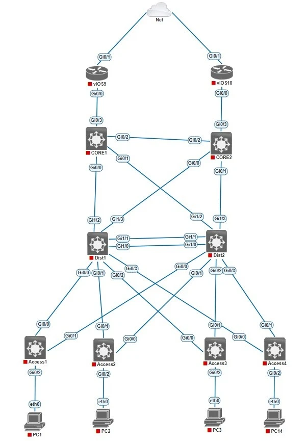
- Make sure Dist1 is the root bridge for VLAN 60,62 Dist2 should be the backup in case Dist1 fails.
- Dist2 is the root bridge for VLAN 61,63 Dist1 should be the backup in case Dist2 fails.
Configuration of Spanning Tree Protocol (STP)
Distribution Switch 1 (Dist1)
Dist1(config)#spanning-tree mode pvst
Dist1(config)#spanning-tree vlan 60 priority 8192
Dist1(config)#spanning-tree vlan 62 priority 8192
Dist1(config)#spanning-tree vlan 61 priority 16384
Dist1(config)#spanning-tree vlan 63 priority 16384
Distribution Switch 2 (Dist2)
Dist1(config)#spanning-tree mode pvst
Dist1(config)#spanning-tree vlan 61 priority 8192
Dist1(config)#spanning-tree vlan 63 priority 8192
Dist1(config)#spanning-tree vlan 60 priority 16384
Dist1(config)#spanning-tree vlan 62 priority 16384
Optional: Enable PortFast on access ports to speed up device bootup
Access1(config)#interface gigabitEthernet 0/2
Access1(config-if)#spanning-tree portfast

Access2(config)#interface gigabitEthernet 0/2
Access2(config-if)#spanning-tree portfast

Access3(config)#interface gigabitEthernet 0/2
Access3(config-if)#spanning-tree portfast

Access4(config)#interface gigabitEthernet 0/2
Access4(config-if)#spanning-tree portfast
Verification Commands
show spanning-tree
show spanning-tree vlan 60
show spanning-tree root
show spanning-tree interface gi0/1 detail
🔜 Next Up: Part 5 – Link Aggregation with EtherChannel for Bandwidth and Redundancy
Part 1: Designing a Scalable Cisco Network Topology: Core, Distribution, and Access Layers
Part 2: Designing a Scalable Cisco Network Topology: Basic Switch Configuration and VLAN Planning.
Part 3: Designing a Scalable Cisco Network Topology: VLANs and Trunk Links Between Switches
Stay Connected and Follow with me