Part 1: Designing a Scalable Cisco Network Topology: Core, Distribution, and Access Layers
 Suresh Thapa
Part 1: Network Topology Overview – Design and Planning
Introduction
Brief about what this series covers.
- Basic Switch Configuration
- VLANs and Trunking
- Spanning Tree Protocol (STP)
- EtherChannel (Link Aggregation)
- Inter-VLAN Routing using Layer 3 Switches or Routers
- Redundancy with HSRP
Static & Dynamic Routing
- NAT and Internet Access
- Connectivity Testing & Troubleshooting
Extra Advanced Topics like DHCP relay via L3 switches, ACLs (Access Control Lists), SNMP/Monitoring setup, Syslog + NTP setup, Port-security, BPDU Guard and QoS concepts for future use
Importance of hierarchical network design (Core-Distribution-Access).
1. Core Layer – The Backbone
- The fastest and most resilient part of the network.
- Provides high-speed, reliable connectivity between distribution switches and to external networks like the internet.
- Typically involves routing and high-throughput switching.
- Example in your topology: vIOS9 and vIOS10 (core routers).
2. Distribution Layer – The Traffic Manager
- Acts as a bridge between the access and core layers.
- Responsible for routing, filtering, and policy enforcement (e.g., access control lists, QoS).
- Also provides redundancy and load balancing.
- Example in your topology: Dist1 and Dist2.
3. Access Layer – The User Connection Point
- Provides direct connectivity to end devices like PCs, printers, and IP phones.
- Handles VLAN assignments, port security, and PoE (if applicable).
- Example in your topology: Access1 to Access2 connected to VPCs.
Using a hierarchical model in network design mirrors how large real-world enterprise networks operate. It allows you to build a solid foundation, isolate faults quickly, and scale services as business needs grow.
Network Diagram
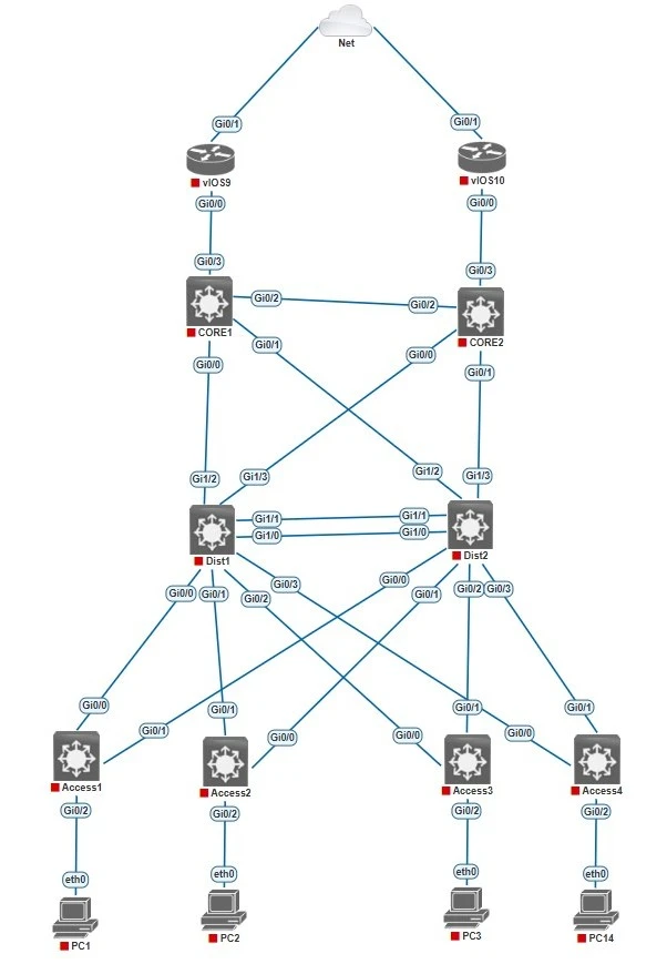
I am using EVE-NG, IOSv-L2 and vIOS.
Device Roles:
| Layer | Device(s) | Description |
|---|---|---|
| ISP | ISP1, ISP2 | Forward Traffic to Internet |
| Core Layer | CORE1, CORE2 | Handle external routing to the ISPs |
| Distribution Layer | Dist1, Dist2 | Interconnect core and access layers |
| Access Layer | Access1 to Access2 | Connect end devices (PC1–PC4) |
IP and VLAN Planning:
| VLAN ID | VLAN Name | IP Address |
|---|---|---|
| 60 | Management | 10.1.60.0/24 |
| 61 | Servers | 10.1.61.0/24 |
| 62 | IT | 10.1.62.0/24 |
| 63 | HR | 10.1.63.0/24 |
| Device | Port | VLAN | Description |
|---|---|---|---|
| Access1 | Gi0/2 | 60 | Management PC |
| Access2 | Gi0/2 | 61 | Server PC |
| Access3 | Gi0/2 | 62 | IT PC |
| Access4 | Gi0/2 | 63 | HR |
| Access to Distribution | Trunk | All | All port will be L2 Trunk ports |
| Distribution to CORE | L3 | None | All Port will be L3 ports |
Goals of This Topology:
- Practice Layer 2 and Layer 3 concepts.
- Implement redundancy and scalability.
- Configure VLANs, STP, HSRP, OSPF, Static routing, and NAT.
Part 2: Designing a Scalable Cisco Network Topology: Basic Switch Configuration and VLAN Planning.
Hostnames, passwords, VLAN creation
Stay Connected and Follow with me
Tags:
Cisco
Network